Basic Power State Monitor (now with final build pics)

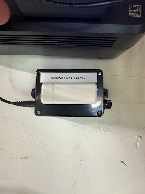
I needed a very basic way to tell if the power has gone out for the outlet to my garage freezer. It is plugged into a GFCI, so if it trips, I’d like to know before food spoils. While you can get GFCI outlets with audible alarms, I’d rather be notified in some way.

Here’s what I came up with:

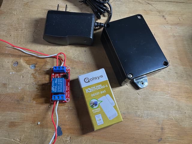
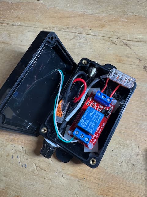
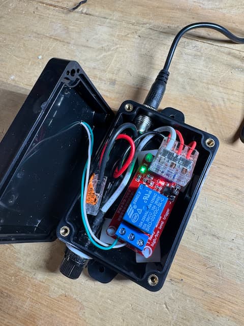
I used a 5v DC power supply, connected to the input of a 5V Relay Module, with a jumper from the + terminal to the input terminal on the relay. This causes the relay to activate when the power is applied.

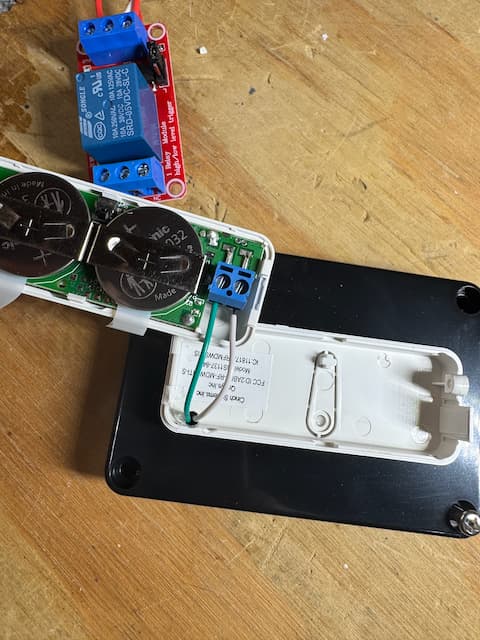
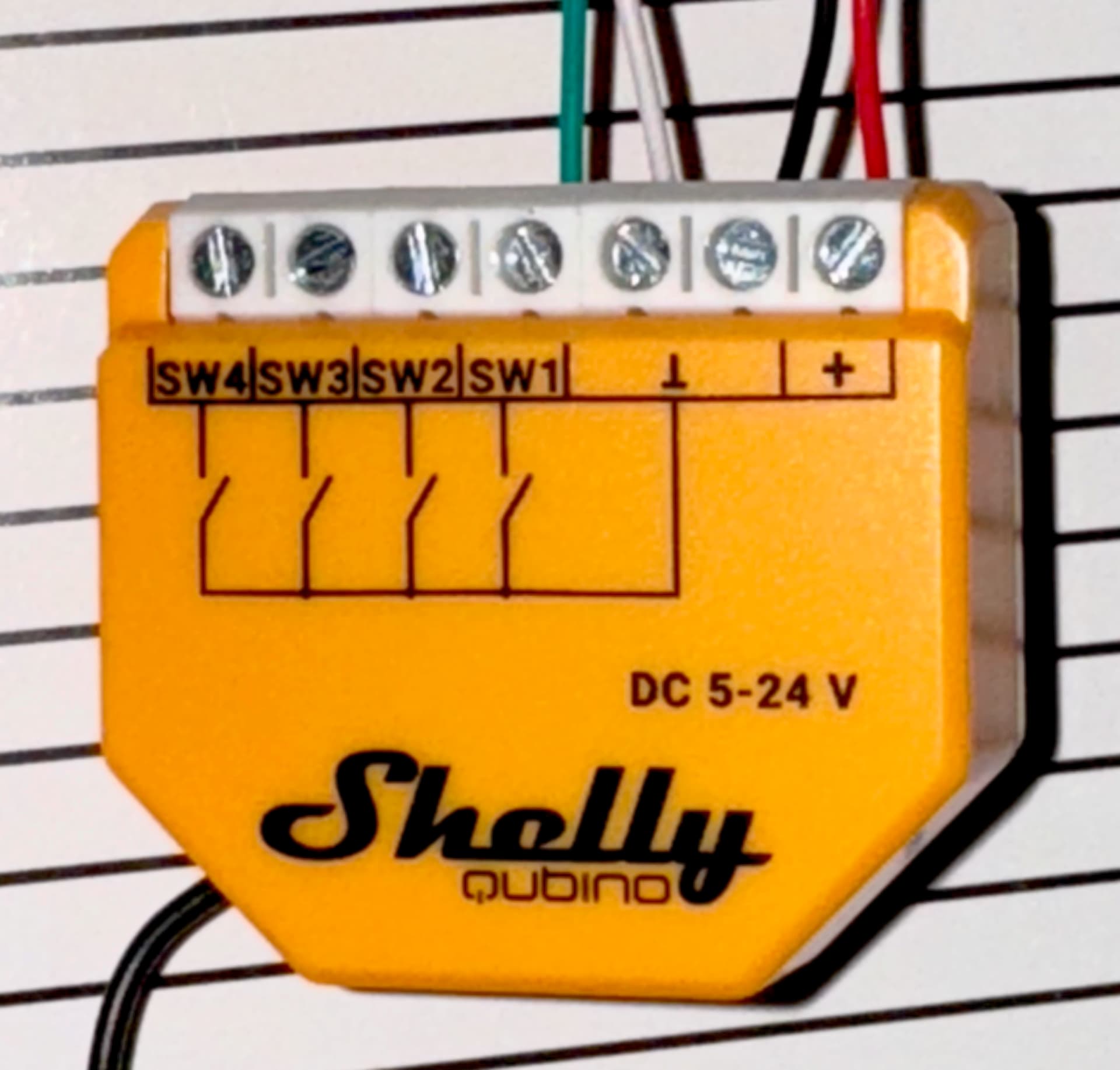
On the other side of the relay, connected the normally open terminals to the external input terminals on a QS1117-840 IQ Door/Window Mini Extended sensor.

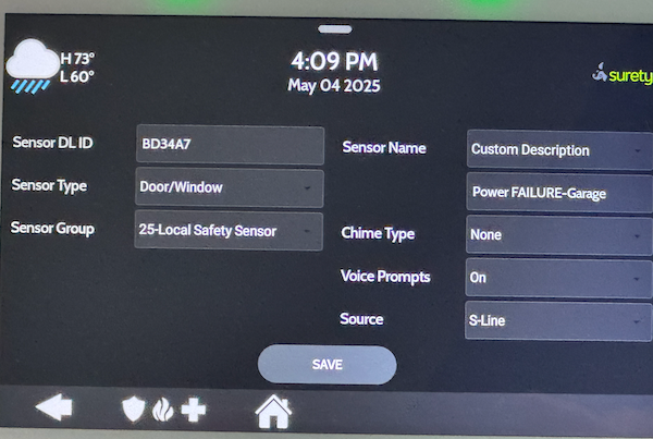
I have the sensor joined to my IQ 4 panel as “Garage Freezer Power Status” in Group 25 (Local Safety Sensor)*. (see note below). I then setup notifications in alarm.com to signal me when this sensor changes state.

Operation
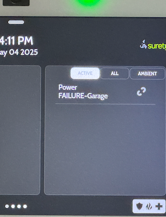
So when the power fails on the 5v supply, the relay module opens, which in turn opens the sensor. Then, I have the IQ Panel set to notify me whenever that sensor opens and report it as a power failure.

Recovery
When the power is re-applied, the relay closes, the sensor closes and the IQ panel announces the closure and sends me another notification.

Implementation
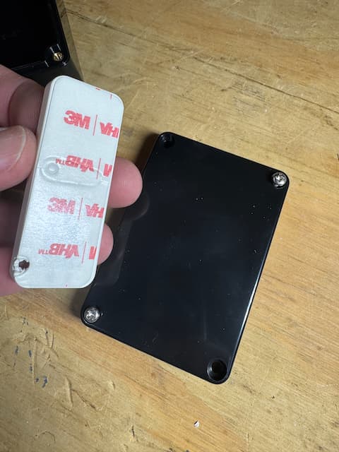
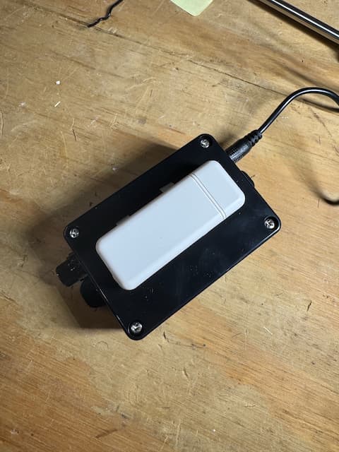
I simply plugged the 5v supply into the same outlet with the freezer. I also purchased a small project box and connectors to make it all look neat.

Parts List:

Variations:
Any other sensor - z-wave, zigbee, etc. That IQ Door sensor could easily be any other type of contact sensor - a Shelly i4, a switch input on a Zooz Z-Wave relay, etc. So this basic solution should work in a variety of scenarios, and can even land in your home automation environment instead of your alarm (home assistant, hubitat, smartthings, etc.).

Almost any alarm panel. I plan on implementing this to monitor the power to my sump pump outlet as well, and in that case I’m just bringing the 5v supply right into my alarm can where my takeover module is. That way I can place the relay in the box and just direct wire it into an open spot on my IQ 16-F Hardwire. The big benefit of this is that I won’t have to go in my crawlspace to replace the sensor battery!

I suppose if I had another panel, like a Vista 20P, etc I could do something similar.

Some Pictures
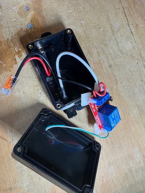
Here’s an ugly picture of the module in a disassembled state while I was still building it on the bench. When I have time I’ll post the final version fully assembled in its project box with the wiring sorted better.

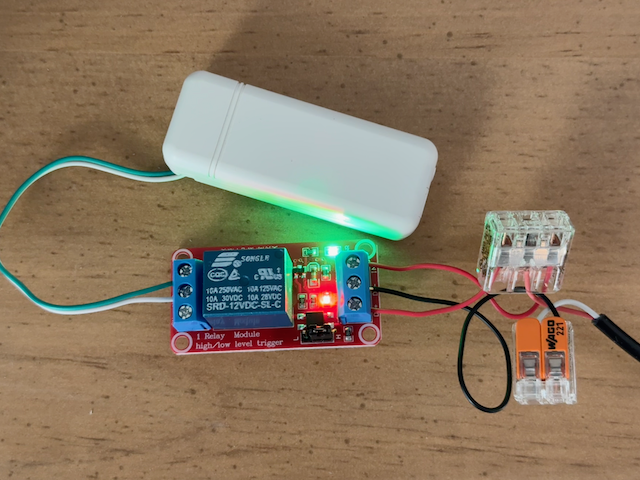
(For those of you with bionic vision, you will notice this picture is a 12v relay not the 5v. This pic is of an earlier prototype that is exactly as above, only 12v. Considering this use case, I thought the lower the voltage the better for the long run.)

Note on the Sensor config in the IQ panel.
I played with several group options for this and while I settled for now on Door/Window Group 25, I’m considering changing this to Heat, Water or Freeze sensor type in Group 25 instead. Those sensor types constantly vocalize on the panel and require a human to acknowledge it to silence. Could be handy in certain circumstances depending on how urgent the power being out really is for your use case. For mine I think the alert via ADC is probably enough.

Update: Final Build

So I finally moved this from the work bench to actual production. Here are some updated pics and what the final version looked like, along with some ideas for expandability.

The Parts

Here’s what I started with:

  • 5V DC Power Supply (which is plugged into the circuit being monitored)
  • IQ Wireless (319) Door/Window Extended Sensor (allows dry contact inputs)
  • 5V Relay that will open contact upon power failure
  • Project box
  • Fuse Assembly w/ 0.5A fuse, and 5.5 x 2.1 mm Socket connector (not pictured)

Mounting the Sensor

Using double-sided tape to attach to the outside lid of the project box. Drilled a hole and connected some #22 wire.

Wiring

I initially wired it up but didn’t love the 2 wires in the same connection spot on the relay. So I used another Wago to reduce it to one wire per connection on the relay. Then stuffed it all in the box. I used standoff mounts for the relay board that had some double-sided tape on the bottom. Had to align all to the right to allow for the jack and fuse assemblies to fit.

  • 5v input goes to the DC+ and DC-, with the + bridged to the IN terminal.
  • Relay jumper set to “high” so when it powers on and senses 5v at the In terminal, the relay closes.
  • On the output side, the NO and COM terminals are connected to the Qolsys sensor. (or whatever z-wave or dry contact sensor you may be using.)

Final Assembly and Mounting

Programming

Added the sensor to the Qolsys IQ4 Panel, choosing the following details:

Type: Door/Window
Group: 25 Local Safety Sensor
I setup voice prompts on, and chime off, but YMMV
Name: Power FAILURE - Garage

Notifications

In alarm.com, setup a notification to tell me when the power is out. Also setup a notification if power remains out for 10 minutes or more. Logic being I would then need to investigate this outage.

Notification Type: Sensor Activity

Notification Type: Sensor Left Open

Operation

When power fails, I get a push notification to my phone, an SMS message and an Email. Also, the open sensor annunciates on the panel, and displays constantly as an open sensor:

Variations

Of course this same principal can be applied a number of ways to other situations, namely:

Alternatives to the IQ Door/Window Wireless Sensor

  • If you have a security panel or takeover in the home, you could hardwire the relay to an open zone on the takeover module.
  • A PowerG sensor could be used (I had one but frankly the 319 sensor was cheaper and I have a pile of them!)
  • You could use this with any home automation system, using an appropriate z-wave, zigbee or other dry contact sensor

Try Other Sensor Types On The IQ

If you want to change the behavior at the IQ 4 Panel itself, you may want to play with these other sensor types.

Most of these announce an open status repeatedly, and keep the alert message up on the panel until someone acknowledges it. Which can be very handy depending on your use case!

With all of them you may want to keep them in Group 25 to prevent your monitoring company from misinterpretation.

  • Water / Flood
  • Freeze
  • High Temp

Other Alarm Systems

This same solution would work with almost any alarm system that accepts dry contacts on a sensor. With some creativity on the notification side, this can be applied well beyond just the IQ4 panel!

Further - this could also be used with almost any Home Automation system.

Home Assistant

I have this running in Home Assistant as well. Where I’m using a Shelly Wave i4 DC to accept the input from the relay and trigger dashboard flags and notifications based on the sensed power failure.

The trick there was getting the Shelly an alternative power source such that it stays up while the monitored power was down. My solution there was to power the Shelly from a separate power source that is on a UPS.

Alternative relay location

Much like the sensor alternative above, if you have a takeover module in a security panel, you could run the 5V from the monitored source into the panel, and locate your relay there. However you’d need to be careful about voltage drop and distance.

Other Notifications / Alerts

Depending on the need, beyond notifications you could turn on/off a light, turn a light RED or other color, etc. Whatever makes sense for your use case.

I do have an additional siren and strobe in my garage so I was thinking of adding a RGB bulb that turns on and glows red when the failure occurs. (yes, I actually have a z-wave RGB smart bulb from 10+ years ago. I wish they still made them!)

Why 5VDC?

This same approach can be adjusted for a variety of voltages. I chose 5V because it was easy, cheap, and low enough that I wasn’t concerned about the cheap relay burning out. However I have built 12V versions of this same solution and they have been working fine for months. However the 12v relay runs a little warmer.